
Computer's Brain - Adders to RAM
It's been a very long time since I have visited this topic.

Adders :
They are the basic functionality of a computer to add 2 binary. There are two types of adders. Half Adders, Full Adders.
Half Adders : They are just XOR gate and AND gate combined. The AND gate is responsible for getting the Carry of Addition. Look at the examples bellow-
A B Output 0 0 0 1 0 1 0 1 1 1 1 10 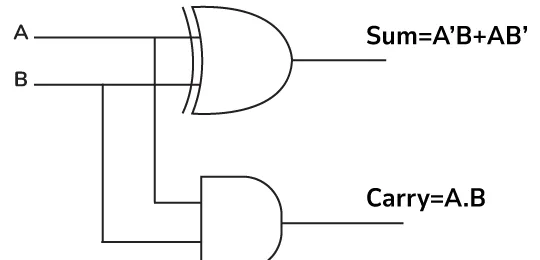
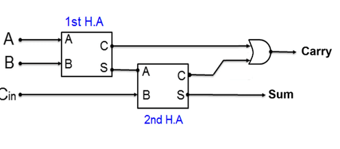
Full Adder : On full adder we tend to take 3 inputs instead of 2,
A,BandCinwhich is carry inInput Output A B Cin Sum Carry 0 0 0 0 0 0 0 1 1 0 0 1 0 1 0 0 1 1 0 1 1 0 0 1 0 1 0 1 0 1 1 1 0 0 1 1 1 1 1 1 A Full Adder combines two Half Adders: the first takes inputs A and B, and the second takes the output from the first along with the carry-in (Cin) from the previous calculation. Finally, the carries from both Half Adders pass through an OR gate to produce the new carry and sum.
Flags Generated by ALU:
The 3 important flags that an ALU generates are
Bit Overflow : It is a condition when the output of the last logic full / half adder has a carryover. This is the same case what happens to pacman after
level 255in which the ALU overflows which cause a bunch of errors and glitches.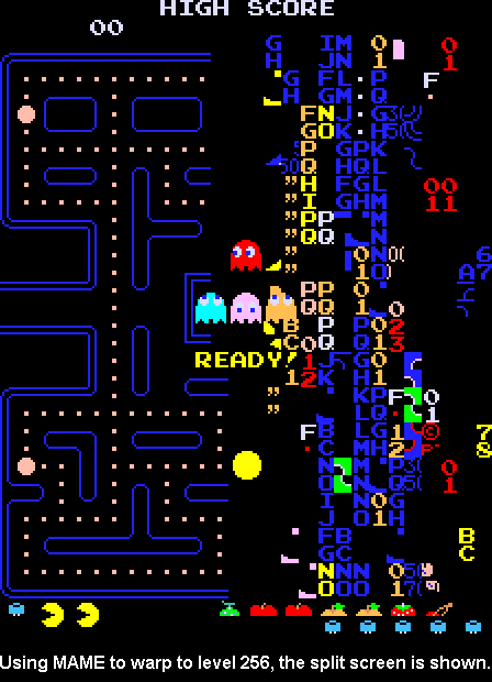
Zero : To check if the output of the ALU is zero the logical unit does a bunch of checks with
ORgates to get one answer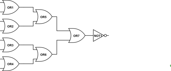
If any of the input is
1the output is going to be0else the output is going to be1.Negative : There is a special flag given by every ALU to check if the given output is negative or not.
Latches
AND OR Latch : It remembers 1 bit of information, there are two inputs going into an AND OR Latch.
1is toSETand2is toResetit. If the set and reset is both tuned off than the output of this latch is whatever the last value was put in.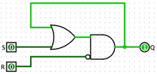
Gated Latch : It has two inputs,
1 Dataand2 Write Enable. When the write enable wire is on the latch changes it's value .
Registers
A group of latches operating at a single time (8 latches mean 1 byte of memory) is called a register.
The number of bits a register can hold is called a width.
Multiplexer
A multiplexer is a combinational circuit that has many data inputs and a single output, depending on control or select inputs.
RAM
RAM has bunch of latches that are arranged in a grid like structure which is inturn powered by a multiplexer.
There are a bunch of wires that connect it to the CPU.
- Address Bus : Address Bus is Uni directional as RAM
neversends the cup an address. - Control Bus : It either
writesthe data to the RAM orreaddata from RAM. - Data Bus : Data bus is
bi directional, it is the wires from where data is transferred to and from theCPU. If the instruction is to read the data of the address1001, the data is going to be sent from the data bus by the ram and vice versa.
Date: 2024-10-09